(Solved): QUESTIONS 1. For amplifier circuit given in Figure i, the opamp unloaded voltage gain is Ay \( =200 ...
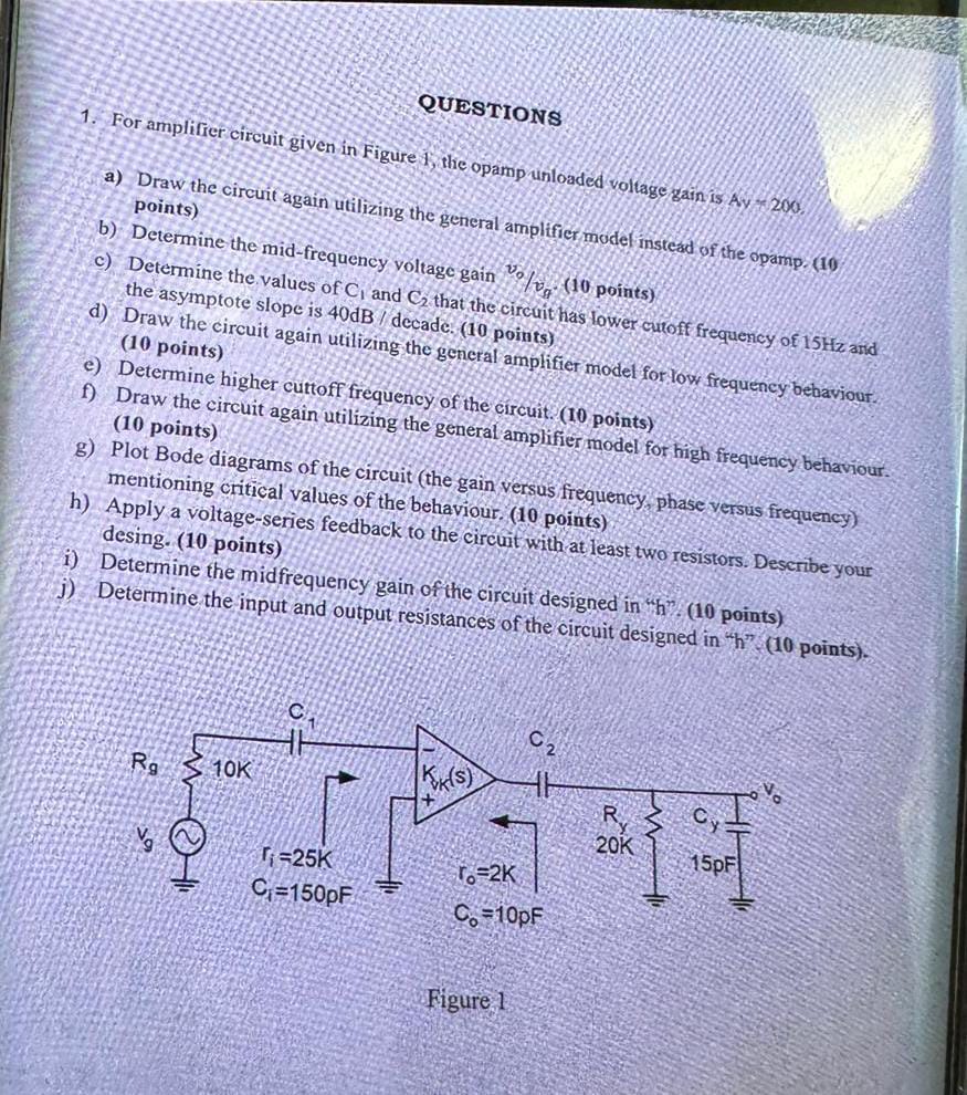
QUESTIONS 1. For amplifier circuit given in Figure i, the opamp unloaded voltage gain is Ay \( =200 \) a) Draw the circuit again utilizing the general amplifier moder instead of the opamp. (10) points) b) Determine the mid-frequency voltage gain \( v_{0} / v_{9} \). ( 10 points) the asymptote slope is \( 40 \mathrm{~B} / \) dece (ilizing the general amplifier model for low frequency bebaviour. d) Draw the c (10 points) e) Determine higher cuttoff frequency of the circuit. ( 10 points) f) Draw the circuit again utilizing the general amplifier model for high frequency behaviour. ( 10 points) g) Plot Bode diagrams of the circuit (the gain versus frequency phase versus frequency) mentioning critical values of the behaviour, ( 10 points) h) Apply a voltage-series feedback to the circuit with at least two resistors. Describe your desing. ( 10 points) i) Determine the midfrequency gain of the circuit designed in "h? ( 10 points) j) Determine the input and output resistances of the circuit designed in \( h \) " \( (10 \) points).