Home /
Expert Answers /
Mechanical Engineering /
questions-q10-q11-relate-to-the-tie-bar-shown-in-fig-4-the-steel-tie-bar-shown-in-fig-4-has-been-pa963
(Solved): Questions Q10-Q11 relate to the tie-bar shown in Fig. 4. The steel tie-bar shown in Fig. 4 has been ...
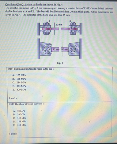
Questions Q10-Q11 relate to the tie-bar shown in Fig. 4. The steel tie-bar shown in Fig. 4 has been designed to earry a tension force of 150 kN when bolted between double brackets at A and B. The bar will be fabricated from 20 mm thick plate. Other dimensions are given in Fig. 4. The diameter of the bolts at
Aand
Bis 35 mm . Q10) The maximum tensile stress in the bar is A. 107 MPa B. 188 MPa C. 214 MPa D. 375 MPa E. 429 MPa 5 marks Q11) The shear stress in the bolts is A. 78 MPa B. 39 MPa C. 156 MPa D. 188 MPa E. 214 MPa 5 marks