(Solved): Seven identical bars, each \( \mathbf{2 m} \) in length and \( \mathbf{1 0 0 0} \mathbf{m m}^{\mathb ...
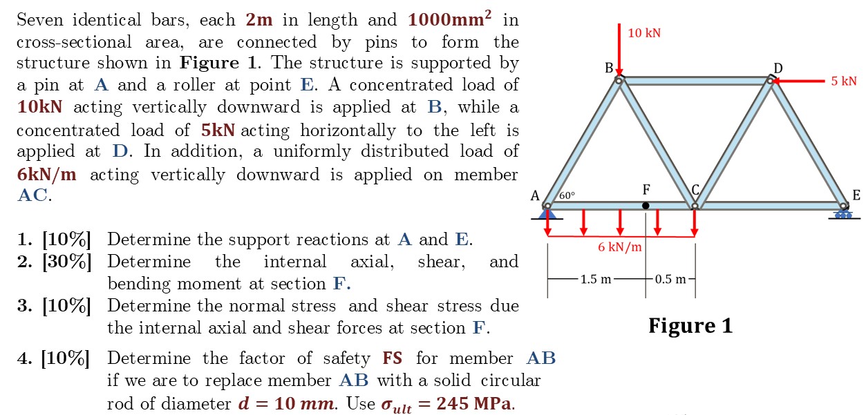
Seven identical bars, each \( \mathbf{2 m} \) in length and \( \mathbf{1 0 0 0} \mathbf{m m}^{\mathbf{2}} \) in cross-sectional area, are connected by pins to form the structure shown in Figure 1. The structure is supported by a pin at \( \mathbf{A} \) and a roller at point \( \mathbf{E} \). A concentrated load of \( \mathbf{1 0 k N} \) acting vertically downward is applied at B , while a concentrated load of \( \mathbf{5 k N} \) acting horizontally to the left is applied at \( \mathbf{D} \). In addition, a uniformly distributed load of \( \mathbf{6 k N} / \mathbf{m} \) acting vertically downward is applied on member AC . 1. [10\%] Determine the support reactions at A and E. 2. [30\%] Determine the internal axial, shear, and bending moment at section \( \mathbf{F} \). 3. [10\%] Determine the normal stress and shear stress due the internal axial and shear forces at section \( \mathbf{F} \). 4. [10\%] Determine the factor of safety FS for member AB if we are to replace member AB with a solid circular rod of diameter \( \boldsymbol{d}=\mathbf{1 0 ~ m m} \). Use \( \boldsymbol{\sigma}_{\text {ult }}=\mathbf{2 4 5 ~ M P a} \).