Home /
Expert Answers /
Electrical Engineering /
t3-4-consider-figure-3-which-shows-the-pi-equivalent-representation-of-a-transmission-line-interco-pa373
(Solved): T3.4 Consider Figure 3 which shows the pi-equivalent representation of a transmission line interco ...
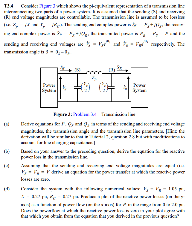
T3.4 Consider Figure 3 which shows the pi-equivalent representation of a transmission line interconnecting two parts of a power system. It is assumed that the sending (S) and receiving (R) end voltage magnitudes are controllable. The transmission line is assumed to be lossless (i.e. \( Z_{p}=j X \) and \( Y_{p}=j B_{C} \) ). The sending end complex power is \( \hat{S}_{S}=P_{S}+j Q_{S} \), the receiving end complex power is \( \hat{S}_{R}=P_{R}+j Q_{R} \), the transmitted power is \( P_{R}=P_{S}=P \) and the sending and receiving end voltages are \( \hat{V}_{S}=V_{S} e^{j \theta_{S}} \) and \( \hat{V}_{R}=V_{R} e^{j \theta_{R}} \) respectively. The transmission angle is \( \delta=\theta_{S}-\theta_{R} \). Figure 3: Problem \( 3.4 \) - Transmission line (a) Derive equations for \( P, Q_{S} \) and \( Q_{R} \) in terms of the sending and receiving end voltage magnitudes, the transmission angle and the transmission line parameters. [Hint: the derivation will be similar to that in Tutorial 2, question \( 2.8 \) but with modifications to account for line charging capacitance.] (b) Based on your answer to the preceding question, derive the equation for the reactive power loss in the transmission line. (c) Assuming that the sending and receiving end voltage magnitudes are equal (i.e. \( V_{S}=V_{R}=V \) derive an equation for the power transfer at which the reactive power losses are zero. (d) Consider the system with the following numerical values: \( V_{S}=V_{R}=1.05 \mathrm{pu} \), \( X=0.27 \mathrm{pu}, B_{C}=0.27 \mathrm{pu} \). Produce a plot of the reactive power losses (on the \( \mathrm{y}- \) axis) as a function of power flow (on the \( \mathrm{x} \)-axis) for \( P \) in the range from 0 to \( 2.0 \mathrm{pu} \). Does the powerflow at which the reactive power loss is zero in your plot agree with that which you obtain from the equation that you derived in the previous question?
Expert Answer
power derivation were done. Reactive po