Home /
Expert Answers /
Electrical Engineering /
task-4-consider-figure-3-given-below-this-rlc-circuit-is-a-bandpass-filter-a-for-r-3-3k-omega-pa975
(Solved): Task #4: Consider Figure 3 given below. This RLC circuit is a bandpass filter. a) For R=3.3k\Omega ...
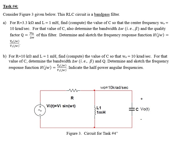
Task #4: Consider Figure 3 given below. This RLC circuit is a bandpass filter. a) For
R=3.3k\Omega and
L=1mH, find (compute) the value of C so that the center frequency
w_(@)=
10kra(d)/(sec). For that value of C , also determine the bandwidth
\Delta w(i.e.,
\beta ) and the quality factor
Q=(w_(0))/(\Delta w)of this filter. Determine and sketch the frequency response function
H(jw)=
(V_(o)(jw))/(V_(i)(jw)). b) For
R=10k\Omega and
L=1mH, find (compute) the value of C so that
w_(0)=10kra(d)/(sec). For that value of C , determine the bandwidth
\Delta w(i.e.,
\beta ) and Q . Determine and sketch the frequency response function
H(jw)=(V_(o)(jw))/(V_(i)(jw)). Indicate the half-power angular frequencies.