Home /
Expert Answers /
Electrical Engineering /
the-circuit-shown-in-figure-6-below-is-a-wheatstone-bridge-circuit-a-using-mesh-analysis-dete-pa953
(Solved): The circuit shown in Figure 6 (below) is a Wheatstone Bridge Circuit. a) Using mesh analysis, dete ...
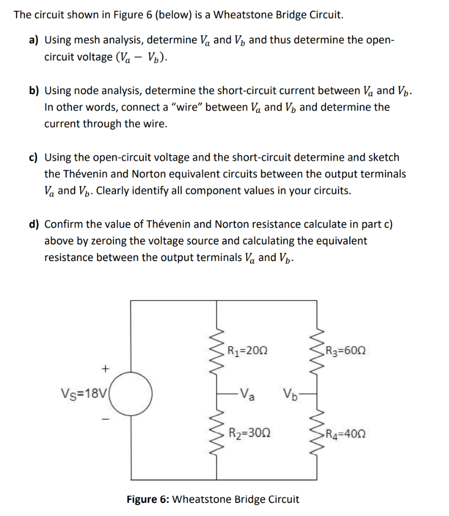
The circuit shown in Figure 6 (below) is a Wheatstone Bridge Circuit. a) Using mesh analysis, determine \( V_{a} \) and \( V_{b} \) and thus determine the opencircuit voltage \( \left(V_{a}-V_{b}\right) \). b) Using node analysis, determine the short-circuit current between \( V_{a} \) and \( V_{b} \). In other words, connect a "wire" between \( V_{a} \) and \( V_{b} \) and determine the current through the wire. c) Using the open-circuit voltage and the short-circuit determine and sketch the Thévenin and Norton equivalent circuits between the output terminals \( V_{a} \) and \( V_{b} \). Clearly identify all component values in your circuits. d) Confirm the value of Thévenin and Norton resistance calculate in part c) above by zeroing the voltage source and calculating the equivalent resistance between the output terminals \( V_{a} \) and \( V_{b} \). Figure 6: Wheatstone Bridge Circuit