Home /
Expert Answers /
Electrical Engineering /
the-current-i-t-flowing-through-the-rlc-circuit-given-in-the-figure-varies-depending-on-the-applie-pa808
(Solved): The current i (t) flowing through the RLC circuit given in the figure varies depending on the applie ...
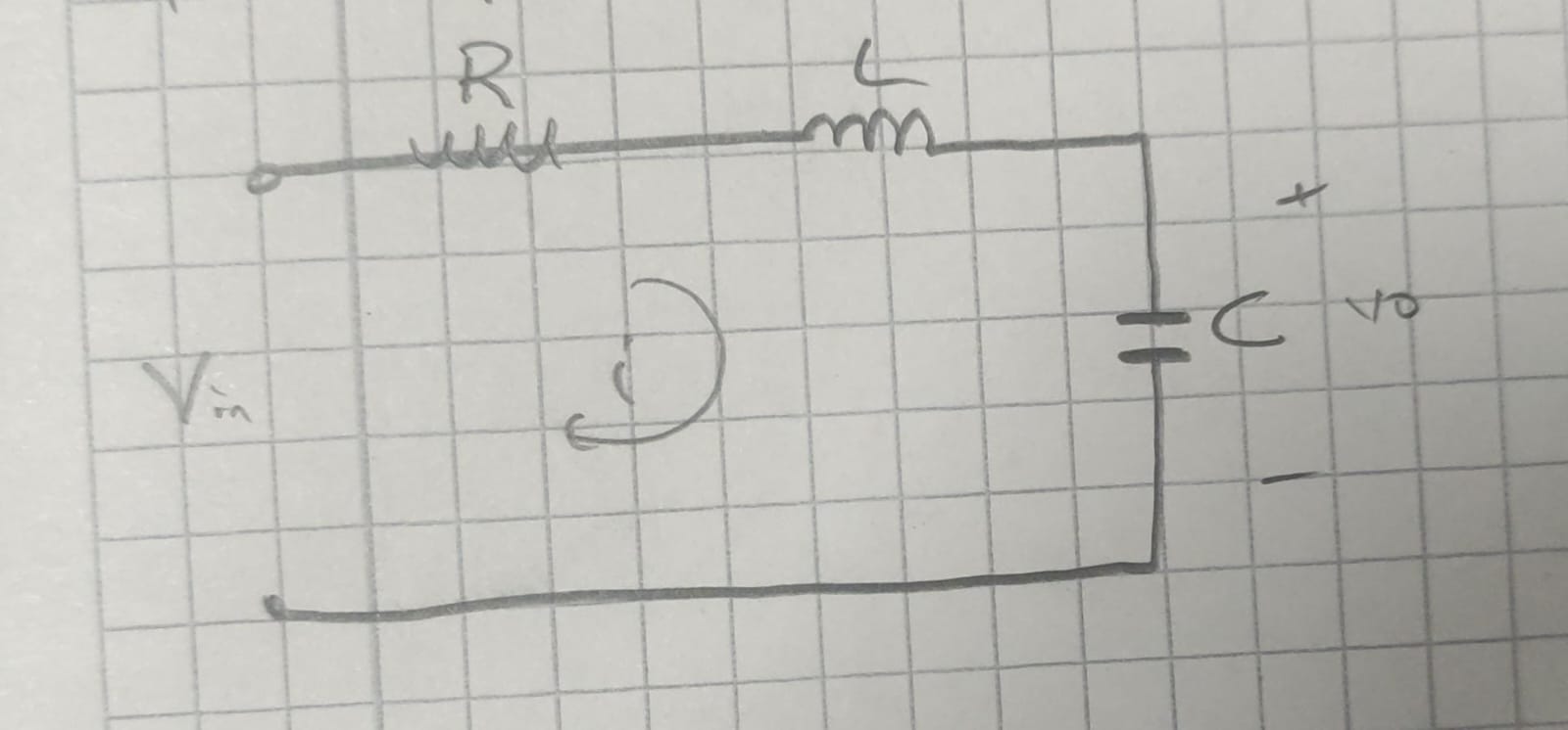
The current i (t) flowing through the RLC circuit given in the figure varies depending on the applied voltage V(t) in this system R = 10 ohm L = 2 H C= 100 F a-) Write the integral differential equation or equations of this system b-) Draw the simulation diagram c-) Obtain the state space model from the simulation diagram d-) Obtain the transfer function