Home /
Expert Answers /
Electrical Engineering /
the-discrete-logic-circuit-depicted-in-the-following-schematic-circuit-7-consists-of-a-jack-j1-pa322
(Solved): The discrete logic circuit depicted in the following schematic (Circuit 7) consists of a jack (J1) ...
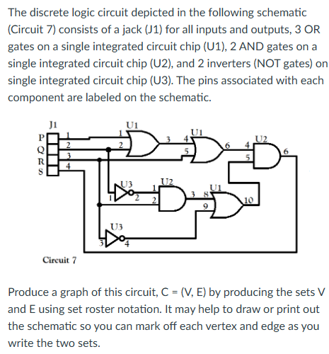
The discrete logic circuit depicted in the following schematic (Circuit 7) consists of a jack (J1) for all inputs and outputs, 3 OR gates on a single integrated circuit chip (U1), 2 AND gates on a single integrated circuit chip (U2), and 2 inverters (NOT gates) on single integrated circuit chip (U3). The pins associated with each component are labeled on the schematic. Crean , Produce a graph of this circuit, \( \mathrm{C}=(\mathrm{V}, \mathrm{E}) \) by producing the sets V and E using set roster notation. It may help to draw or print out the schematic so you can mark off each vertex and edge as you write the two sets.