Home /
Expert Answers /
Physics /
the-electrical-circuit-diagram-below-illustrates-a-15-v-source-connected-to-a-20-w-ohm-resistor-pa419
(Solved): . The electrical circuit diagram below illustrates a 15 V source connected to a 20 W (Ohm) resistor. ...
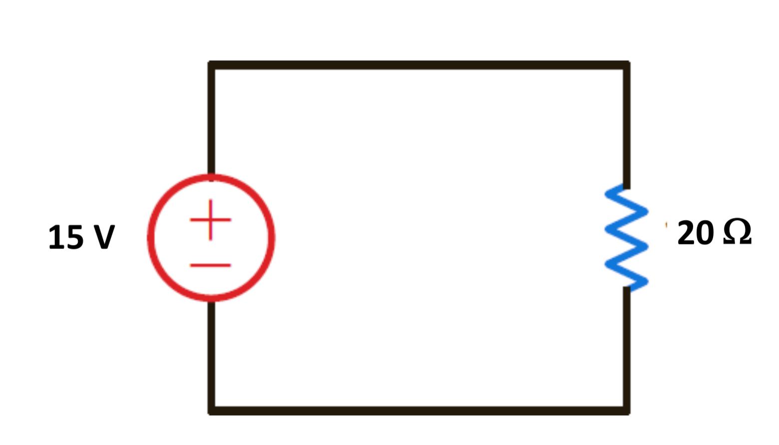
. The electrical circuit diagram below illustrates a 15 V source connected to a 20 W (Ohm) resistor.
 |
|
|
|
a. Using Ohm’s Law, calculate the current going through the resistor.
B. You continuously (linearly) shift the voltage from 9 V to -9 V. On the axes below, graph the voltage (x-axis) versus the expected current (y-axis) going through the resistor. (Make sure to label the graph appropriately.)

C. The result in (b) should be a line. What is the slope of the line? How is the slope of this line related to the resistance?
D.If the resistor were 12 M?, how much current would pass through it?
Expert Answer
A. Using Ohm's Law (V = IR), the current going through the resistor can be calculated by dividing the voltage (15 V) by the resistance