Home /
Expert Answers /
Chemical Engineering /
the-figure-below-shows-a-fluid-flow-system-that-is-designed-to-pump-carbon-tetrachloride-at-20c-pa146
(Solved): The figure below shows a fluid flow system that is designed to pump carbon tetrachloride at 20C ...
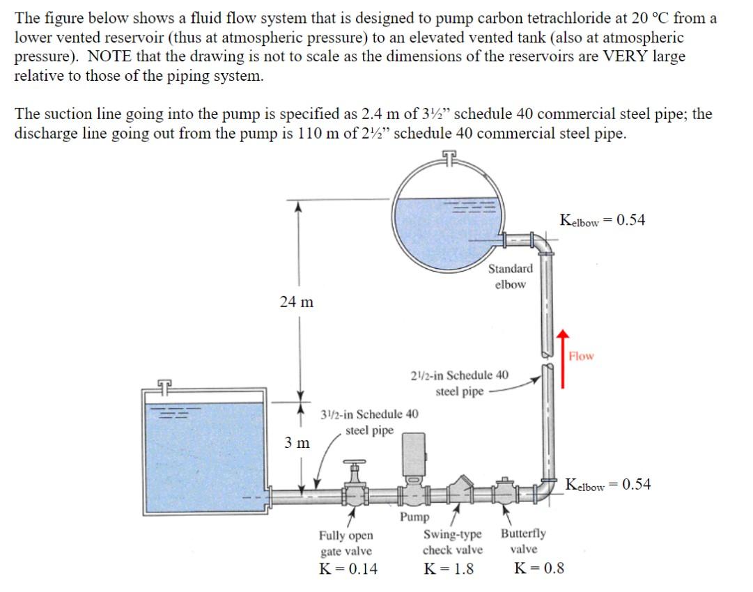
The figure below shows a fluid flow system that is designed to pump carbon tetrachloride at from a lower vented reservoir (thus at atmospheric pressure) to an elevated vented tank (also at atmospheric pressure). NOTE that the drawing is not to scale as the dimensions of the reservoirs are VERY large relative to those of the piping system. The suction line going into the pump is specified as of " schedule 40 commercial steel pipe; the discharge line going out from the pump is of schedule 40 commercial steel pipe.
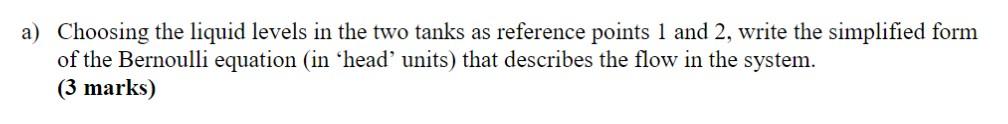
a) Choosing the liquid levels in the two tanks as reference points 1 and 2, write the simplified form of the Bernoulli equation (in 'head' units) that describes the flow in the system. (3 marks)
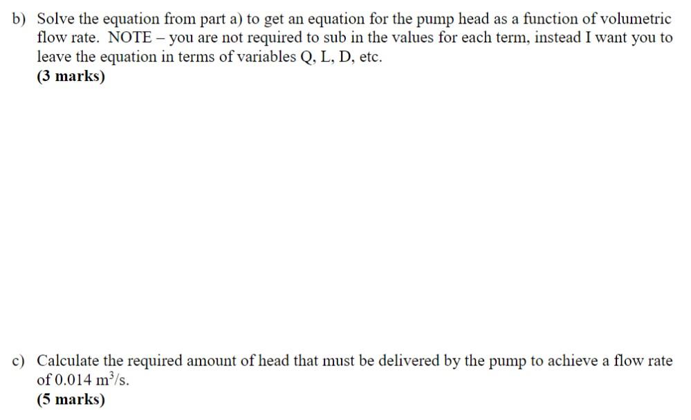
b) Solve the equation from part a) to get an equation for the pump head as a function of volumetric flow rate. NOTE - you are not required to sub in the values for each term, instead I want you to leave the equation in terms of variables , etc. (3 marks) c) Calculate the required amount of head that must be delivered by the pump to achieve a flow rate of . (5 marks)
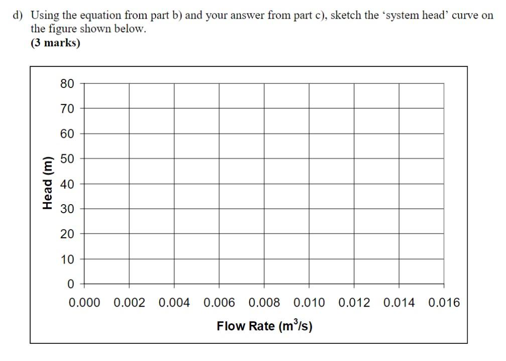
d) Using the equation from part b) and your answer from part c), sketch the 'system head' curve on the figure shown below. (3 marks)
Expert Answer
ANSWER....a) Write the Bernoulli expression for points 1 and 2:p1?g+v122g+z1=p2?g+v222g+z2+h1?? For liquid levels in the two