Home /
Expert Answers /
Electrical Engineering /
the-figure-below-shows-a-simple-diagram-for-deriving-the-model-of-a-dc-servomotor-which-is-a-rotati-pa377
(Solved): The figure below shows a simple diagram for deriving the model of a DC servomotor, which is a rotati ...
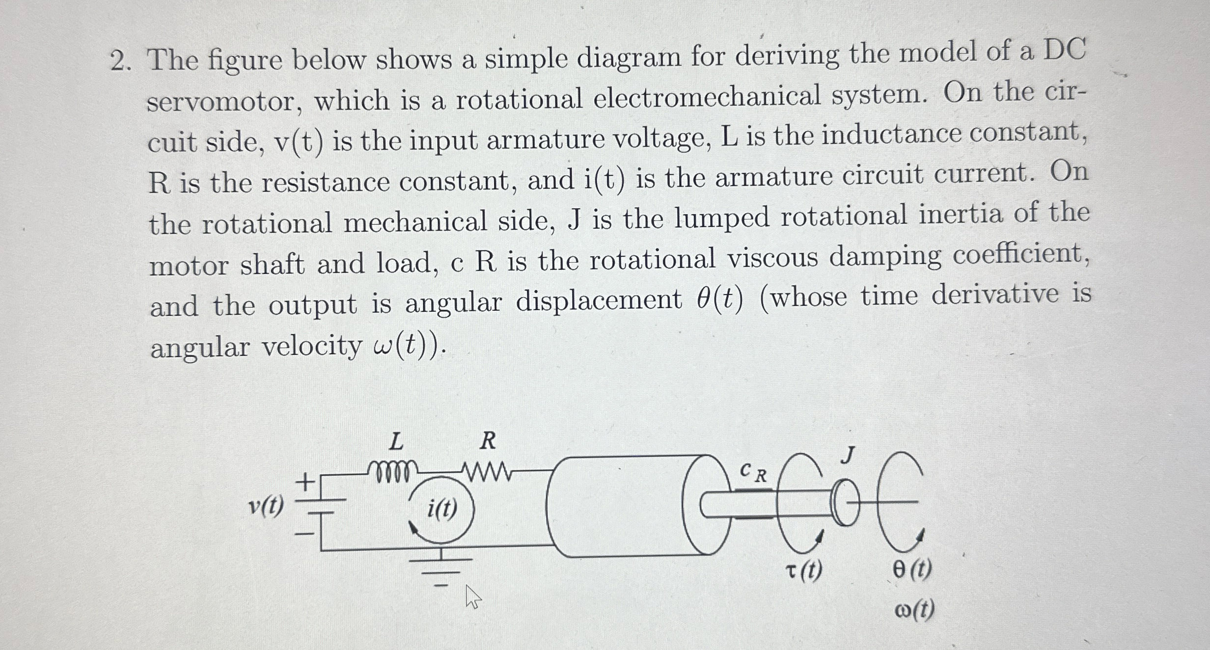
The figure below shows a simple diagram for deriving the model of a DC servomotor, which is a rotational electromechanical system. On the cir- cuit side,
v(t)is the input armature voltage, L is the inductance constant,
Ris the resistance constant, and
i(t)is the armature circuit current. On the rotational mechanical side, J is the lumped rotational inertia of the motor shaft and load, c R is the rotational viscous damping coefficient, and the output is angular displacement
\theta (t)(whose time derivative is angular velocity
\omega (t).