Home /
Expert Answers /
Electrical Engineering /
the-following-figure-shows-an-hb-inverter-used-to-inject-power-to-the-grid-which-is-tied-to-the-gr-pa957
(Solved): The following figure shows an HB inverter used to inject power to the grid, which is tied to the gr ...
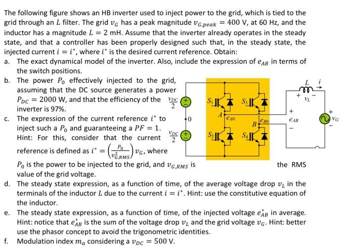
The following figure shows an inverter used to inject power to the grid, which is tied to the grid through an filter. The grid has a peak magnitude , at , and the inductor has a magnitude . Assume that the inverter already operates in the steady state, and that a controller has been properly designed such that, in the steady state, the injected current , where is the desired current reference. Obtain: a. The exact dynamical model of the inverter. Also, include the expression of in terms of the switch positions. b. The power effectively injected to the g? assuming that the source generates a pov , and that the efficiency of the inverter is . c. The expression of the current reference to inject such a and guaranteeing a . Hint: For this, consider that the current reference is defined as , where is the power to be injected to the grid, and value of the grid voltage. d. The steady state expression, as a function of time, of the average voltage drop in the terminals of the inductor due to the current . Hint: use the constitutive equation of the inductor. e. The steady state expression, as a function of time, of the injected voltage in average. Hint: notice that is the sum of the voltage drop and the grid voltage . Hint: better use the phasor concept to avoid the trigonometric identities. f. Modulation index considering a .