Home /
Expert Answers /
Electrical Engineering /
the-schematic-diagram-shown-in-figure-6-shows-a-ternary-full-adder-that-receives-two-ternary-digits-pa204
(Solved): The schematic diagram shown in Figure 6 shows a ternary full adder that receives two ternary digits ...
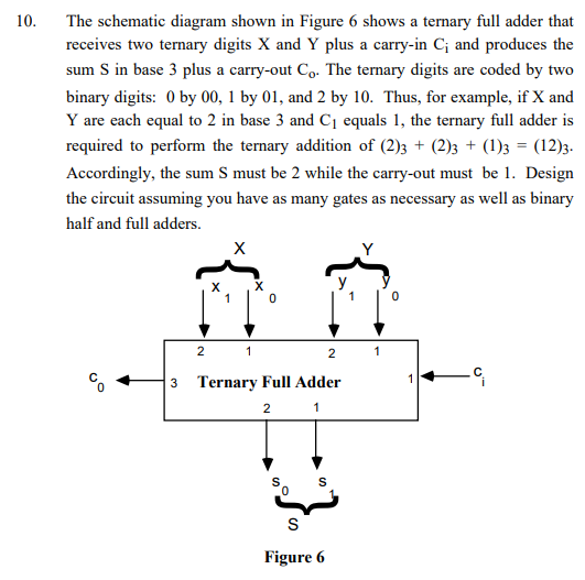
The schematic diagram shown in Figure 6 shows a ternary full adder that receives two ternary digits and plus a carry-in and produces the sum in base 3 plus a carry-out . The ternary digits are coded by two binary digits: 0 by 00,1 by 01 , and 2 by 10 . Thus, for example, if and are each equal to 2 in base 3 and equals 1 , the ternary full adder is required to perform the ternary addition of . Accordingly, the sum must be 2 while the carry-out must be 1 . Design the circuit assuming you have as many gates as necessary as well as binary half and full adders.