Home /
Expert Answers /
Civil Engineering /
the-side-elevation-of-the-retaining-wall-shows-a-typical-solution-adopted-for-a-retaining-wall-in-pa631
(Solved): The side elevation of the retaining wall shows a typical solution adopted for a retaining wall in ...
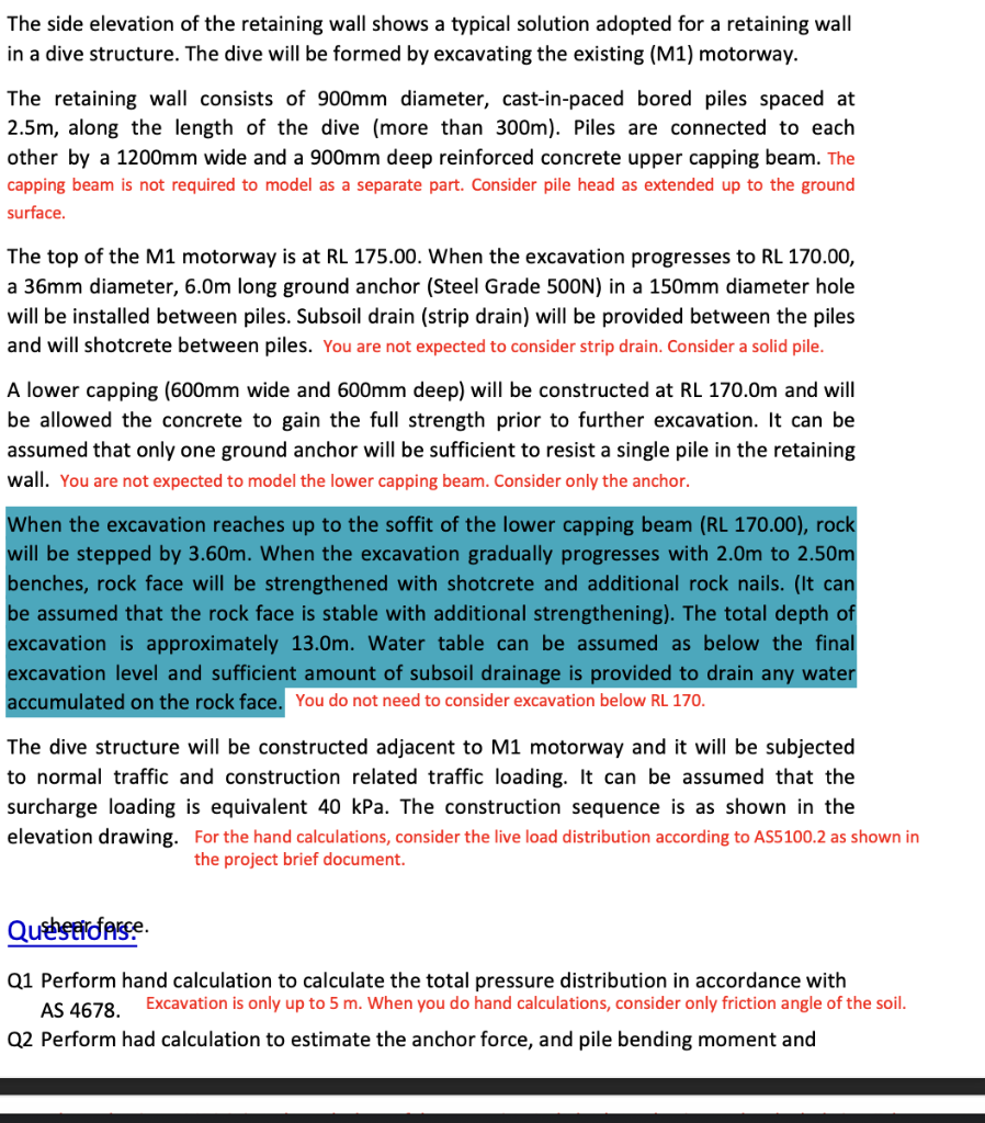
The side elevation of the retaining wall shows a typical solution adopted for a retaining wall in a dive structure. The dive will be formed by excavating the existing (M1) motorway. The retaining wall consists of \( 900 \mathrm{~mm} \) diameter, cast-in-paced bored piles spaced at \( 2.5 \mathrm{~m} \), along the length of the dive (more than \( 300 \mathrm{~m} \) ). Piles are connected to each other by a \( 1200 \mathrm{~mm} \) wide and a \( 900 \mathrm{~mm} \) deep reinforced concrete upper capping beam. The capping beam is not required to model as a separate part. Consider pile head as extended up to the ground surface. The top of the \( \mathrm{M} 1 \) motorway is at RL 175.00. When the excavation progresses to \( \mathrm{RL} 170.00 \), a \( 36 \mathrm{~mm} \) diameter, \( 6.0 \mathrm{~m} \) long ground anchor (Steel Grade \( 500 \mathrm{~N} \) ) in a \( 150 \mathrm{~mm} \) diameter hole will be installed between piles. Subsoil drain (strip drain) will be provided between the piles and will shotcrete between piles. You are not expected to consider strip drain. Consider a solid pile. A lower capping (600mm wide and \( 600 \mathrm{~mm} \) deep) will be constructed at \( \mathrm{RL} 170.0 \mathrm{~m} \) and will be allowed the concrete to gain the full strength prior to further excavation. It can be assumed that only one ground anchor will be sufficient to resist a single pile in the retaining wall. You are not expected to model the lower capping beam. Consider only the anchor. When the excavation reaches up to the soffit of the lower capping beam (RL 170.00), rock will be stepped by \( 3.60 \mathrm{~m} \). When the excavation gradually progresses with \( 2.0 \mathrm{~m} \) to \( 2.50 \mathrm{~m} \) benches, rock face will be strengthened with shotcrete and additional rock nails. (It can be assumed that the rock face is stable with additional strengthening). The total depth of excavation is approximately \( 13.0 \mathrm{~m} \). Water table can be assumed as below the final excavation level and sufficient amount of subsoil drainage is provided to drain any water accumulated on the rock face. You do not need to consider excavation below RL 170. The dive structure will be constructed adjacent to \( M 1 \) motorway and it will be subjected to normal traffic and construction related traffic loading. It can be assumed that the surcharge loading is equivalent \( 40 \mathrm{kPa} \). The construction sequence is as shown in the elevation drawing. For the hand calculations, consider the live load distribution according to AS5100.2 as shown in the project brief document. Quesefforse. Q1 Perform hand calculation to calculate the total pressure distribution in accordance with AS 4678. Excavation is only up to \( 5 \mathrm{~m} \). When you do hand calculations, consider only friction angle of the soil, Q2 Perform had calculation to estimate the anchor force, and pile bending moment and