Home /
Expert Answers /
Electrical Engineering /
use-matlab-antenna-azimuth-position-control-system-the-layout-and-schematic-for-an-antenna-azimuth-pa159
(Solved): USE MATLAB Antenna Azimuth Position Control System The layout and schematic for an antenna azimuth ...
USE MATLAB
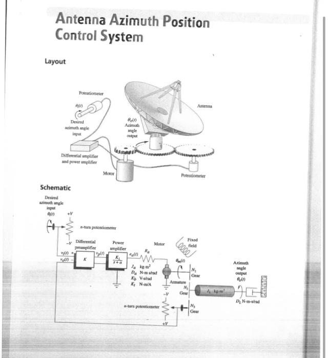
Antenna Azimuth Position Control System
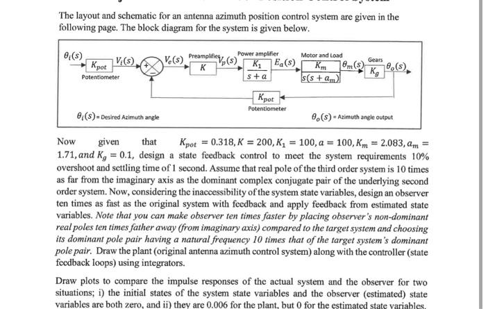
The layout and schematic for an antenna azimuth position control system are given in the following page. The block diagram for the system is given below. Now given that \( K_{p o t}=0.318, K=200, K_{1}=100, a=100, K_{m}=2.083, a_{m}= \) \( 1.71 \), and \( K_{g}=0.1 \), design a state feedback control to meet the system requirements \( 10 \% \) overshoot and scttling time of 1 second. Assume that real pole of the third order system is 10 times as far from the imaginary axis as the dominant complex conjugate pair of the underlying second order system. Now, considering the inaccessibility of the system state variables, design an observer ten times as fast as the original system with feedback and apply feedback from estimated state variables. Note that you can make observer ten times faster by placing observer's non-dominant real poles ten times father away (from imaginary axis) compared to the target system and choosing its dominant pole pair having a natural frequency 10 times that of the target system's dominant pole pair. Draw the plant (original antenna azimuth control system) along with the controller (state fecdback loops) using integrators. Draw plots to compare the impulse responses of the actual system and the observer for two situations; i) the initial states of the system state variables and the observer (estimated) state variables are both zero, and ii) they are \( 0.006 \) for the plant, but 0 for the estimated state yariables.
Expert Answer
Please see the above explanation