Home /
Expert Answers /
Electrical Engineering /
use-verilog-hdl-code-coding-exercise-1-design-a-4-bit-adder-subtractor-like-the-figure-seen-below-pa953
(Solved): Use Verilog HDL code Coding Exercise 1: Design a 4-bit Adder/Subtractor like the figure seen below. ...
Use Verilog HDL code
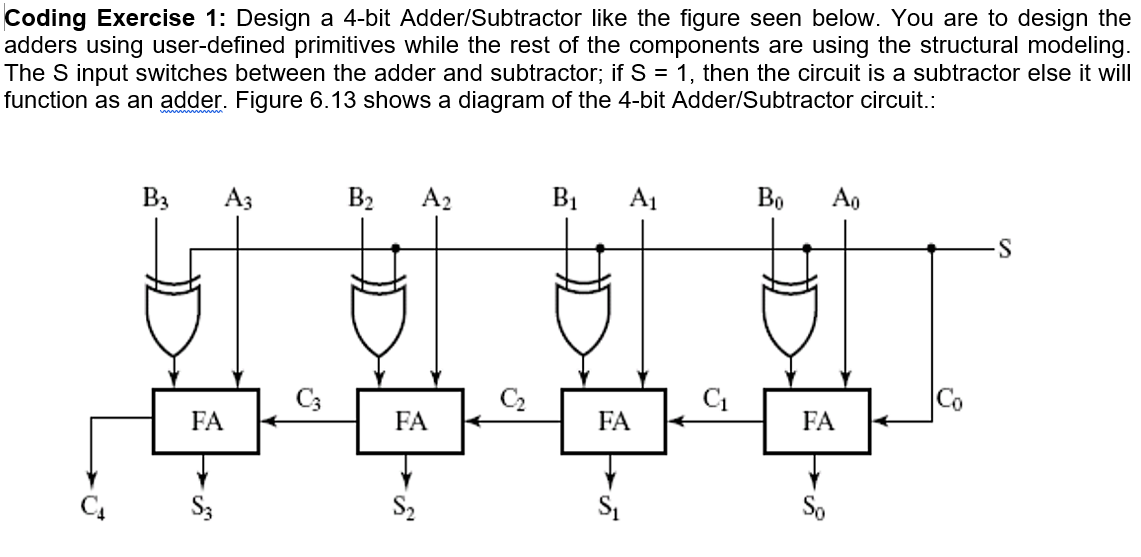
Coding Exercise 1: Design a 4-bit Adder/Subtractor like the figure seen below. You are to design the adders using user-defined primitives while the rest of the components are using the structural modeling. The \( S \) input switches between the adder and subtractor; if \( S=1 \), then the circuit is a subtractor else it will function as an adder. Figure \( 6.13 \) shows a diagram of the 4-bit Adder/Subtractor circuit.:
Expert Answer
Code: module four_bit_adder_subtractor(a,b,M,S,C); input [3:0]a,b; input M; output reg [3:0]S; output reg C; wire C1,C2,C3,C4; wire [3:0]